- Categories
- Categories
- New & Hot Products
- Engine Swap Parts
- Categories / Engine Swap Parts
- Also in Engine Swap Parts
- Accessory Drive Brackets and Kits
- Exhaust Systems
- Gen III Hemi Swap Systems
- Mounts and Crossmembers
- Swap Accessories
- View All
- Marine and Powersports
- Categories / Marine and Powersports
- Also in Marine and Powersports
- Personal Watercraft
- Small Engine
- View All
- Air & Fuel Delivery
- Categories / Air & Fuel Delivery
- Also in Air & Fuel Delivery
- Air Cleaners
- Air Scoops
- Cold Air Intake
- Fuel System Kits
- Fuel Tanks and Fuel Cells
- HydraMat
- View All
- Exhaust
- Nitrous
- Categories / Nitrous
- Also in Nitrous
- Bottles and Accessories
- Controllers and Accessories
- Direct Port Systems
- Distribution Blocks, Filters, Adapters and Fittings
- Electrical and Wiring
- Fuel Pumps and Regulators
- Gauges
- Hose Lines and Tubing
- Intercooler Sprayers
- Microswitch and Solenoid Mounting Brackets
- NOS Jets
- Nitrous Blowdown Hoses and Tubes
- Nitrous Plates
- Nozzles
- Purge Kits
- Refill Kits and Components
- Solenoids and Solenoid Service Parts
- Tools
- View All
- Apparel & Collectibles
- Categories / Apparel & Collectibles
- Also in Apparel & Collectibles
- Backpacks
- Banners
- Clocks
- Decals
- Diecast
- Drinkware
- Face Masks & Gaiters
- Headwear
- Hitch Cover
- Hoodies
- Jackets
- Ladies Apparel
- Literature
- Metal Signs
- Misc
- Pet Accessories
- Polo Shirts
- Shop Shirt
- Sunglasses
- Tote Bags
- Youth Apparel
- View All
- Exterior
- Categories / Exterior
- Also in Exterior
- Convertible Tops and Components
- Decklid Panels
- Doors
- Fenders
- Firewall, Cowl, and Front Unibody
- Floor Pan and Frame
- Fuel Doors
- Graphic Kits
- Grilles
- Hood
- Lighting
- Mini Tub Kits
- Plate Frames and Accessories
- Quarter Panels
- Radiator Supports
- Rear Spoilers
- Rocker Panel
- Roof Panel
- Trim and Moldings
- Truck Bed & Parts
- Truck Cab & Parts
- Valances
- Weatherstrip
- Window and Windshield
- View All
- Off-Road
- AC and Heating
- Categories / AC and Heating
- Also in AC and Heating
- Controls and Cables
- Filler and Delete Panels
- Heater Box and Hoses
- Heater Core
- View All
- EV Conversions
- Categories / EV Conversions
- Also in EV Conversions
- Conversion Brackets and Accessories
- Displays
- High Voltage Contactors
- High Voltage Disconnects
- Power Distribution (PDU)
- Sensors, Connectors, and Accessories
- Vehicle Controls (VCU)
- Wiring Harnesses
- View All
- Plumbing AN Fittings and Hose
- Categories / Plumbing AN Fittings and Hose
- Also in Plumbing AN Fittings and Hose
- Adapters
- All Hose Groups
- Application Specific Parts
- Catch Tanks
- Fuel System Components
- Hose Ends
- Hose Protection, Sleeving & Clamps
- Mr Gasket Push-On
- Mr Gasket Swivel
- Oil & Cooling Systems
- Plumbing Tools
- Power Steering
- Premade Hoses
- Seals
- Super Stock
- Ultra Flex
- UltraPro
- Valves
- Weld-ons and Fill Caps
- View All
- Brakes
- Fasteners and Hardware
- Categories / Fasteners and Hardware
- Also in Fasteners and Hardware
- Quarter Turn Fasteners
- Safety Wire
- Transmission and Drivetrain
- Wheel and Tire
- View All
- Restoration
- Categories / Restoration
- Also in Restoration
- Air Conditioning and Heating
- Air and Fuel Delivery
- Books, Manuals & Brochures
- Brakes
- Bumper
- Convertible Tops and Components
- Cooling
- Decals Labels & Tags
- Electrical
- Engine & Transmission Mounting
- Exhaust
- Fender Covers
- Fuel Tanks & Components
- Ignition
- Lamps & Lighting
- Longbed to Shortbed Conversion Kits
- Radios & Stereos
- Suspension & Steering
- Trailer Hitches
- Transmission & Drivetrain
- Weatherstrip & Rubber
- Wheels & Accessories
- Windows & Windshield
- Wood Bed Floor and Trim
- View All
- Carburetors
- Gaskets
- Safety Equipment
- Categories / Safety Equipment
- Also in Safety Equipment
- Aprons
- Arm Restraints
- Chest and Rib Protectors
- Cleaners
- Drag Parachutes
- Equipment Bags
- Head and Neck Restraints
- Seats
- Shifter Boots
- Shoes
- Tow Straps
- Undergarments
- Window Nets
- Youth
- View All
- Cataclean
- Categories / Cataclean
- Gauges and Gauge Accessories
- Categories / Gauges and Gauge Accessories
- Also in Gauges and Gauge Accessories
- Gauge Accessories and Harnesses
- Gauge Adapters and Fittings
- Shift Lights
- Tach Adapters
- View All
- Suspension & Chassis
- Categories / Suspension & Chassis
- Also in Suspension & Chassis
- Air Ride
- Body Mounts and Hardware
- C-Notch Kits
- Driveshaft Safety Loops
- Front Drop Axles & Kingpins
- Hitches and Towing
- Leveling and Lift Kits
- Longbed to Shortbed Conversion Kits
- Roll Cage Kits
- Shocks and Struts
- Springs & Bumpstops
- Strut Tower and Chassis Braces
- Sway Bars and Components
- Traction Bars and Components
- View All
- Cooling
- Ignition
- Tools, Shop Equipment & Chemicals
- Categories / Tools, Shop Equipment & Chemicals
- Also in Tools, Shop Equipment & Chemicals
- Diagnostic Tools
- Engine Tools
- Extra Long Fender Covers
- Fender Covers
- Fluid Tools
- Front End Covers
- Hand Tools
- Jumbo Fender Covers
- Oils, Fluids, & Additives
- Paint & Dye
- Shop Tools
- Trailer Tools
- View All
- Data Acquisition
- Categories / Data Acquisition
- Also in Data Acquisition
- Cables
- Modules
- Power Distribution Modules
- Sensors
- Sensors With Modules
- Wiring Accessories
- View All
- Intake Manifolds
- Categories / Intake Manifolds
- Carbureted Intake Manifolds
- Carburetor and Manifold Combos
- EFI Intake Manifolds
- Installation Parts and Accessories
Also in Intake Manifolds- Roots Supercharger Intake Manifolds
- View All
- Transmission & Drivetrain
- Categories / Transmission & Drivetrain
- Also in Transmission & Drivetrain
- Internal Components
- Rear Axle & Differential
- Transmission Controller
- Transmission Coolers
- Transmission Mounts
- Transmission Pans and Dipsticks
- Transmission Swap Parts
- Transmissions
- View All
- EFI - Fuel Injection
- Categories / EFI - Fuel Injection
- Also in EFI - Fuel Injection
- AEM EFI
- Atomic EFI
- EFI Distributors
- EFI Fuel System Components
- Gauges and Displays
- Harnesses
- Hilborn EFI and MFI Systems
- Hilborn Service Components
- Injectors
- Legacy EFI
- Modules and Sensors
- Terminator EFI
- Throttle Bodies
- Wiring Shop
- View All
- Interior
- Tuners and Programmers
- Categories / Tuners and Programmers
- Also in Tuners and Programmers
- Accessories
- Amp'd Throttle Booster
- Dinan Software-Tuning
- Inline Tuning Modules
- PCM
- View All
- Electrical
- Lighting
- Categories / Lighting
- Also in Lighting
- Bezels and Trim
- LED Light Bars
- LED Work Lights
- Marker and Signal Lamps
- Tail Lights
- View All
- Wheels and Wheel Accessories
- Categories / Wheels and Wheel Accessories
- Engine
- LS Power
- Categories / LS Power
- Also in LS Power
- EFI Components
- Engine and Transmission mounts
- Fuel Pump Regulator and Filter
- Fuel Tanks
- LS Accessory Drive Brackets and Kits
- LS Drivetrain
- LS Engine Components
- LS Gaskets
- LS Ignition Products
- LS Swap Oil Pans
- LS Swap Radiators
- LS Throttle Bodies
- LS Tools
- LS Valve Covers & Engine Appearance
- LS and LT Nitrous Systems
- View All
-
- Brands
- Brands
- ACCEL
- DiabloSport
- Holley RetroBright
- REKUDO
- ADS
- Dinan
- Hooker
- REV Wheels
- AEM
- Drake Muscle Cars
- Hooker BlackHeart
- Rocket Racing Wheels
- AEM EV
- Earl's
- Hurst
- Scott Drake
- Amp'd
- Edge
- Lakewood
- Simpson Motorcycle
- Anvil Off-Road
- Fender Gripper
- Legendary Wheels
- Simpson Racing
- APR
- Flowmaster
- Mallory
- Sniper
- B&M
- Flowmonster
- Mr. Gasket
- SPAL Fans
- Baer Brakes
- Flowtech Exhaust
- MSD
- Speartech
- Brawler
- Frostbite Cooling
- NOS
- Stilo
- Bright Earth
- Garrett Turbochargers
- ProConnect
- Street Fire
- Brothers Trucks
- Halibrand
- Proforged
- Superchips
- Carroll Shelby Wheels
- HANS
- Pulsar
- Weiand
- CataClean
- Hays
- Quick Fuel Technology
- White Box
- Classic Instruments
- Hilborn
- Quick Time
- XDR
- Demon
- HK Wheels
- Racepak
-
- Detroit Speed
- Holley
- RaceQuip
-
- DeWitts
- Holley EFI
- Range Technology
-
- Shop By Vehicle
- Shop By Vehicle
- Deals
Set Your Timing
- How to set your ignition timing
- Distribution Operation
- Timing Settings
- Tools and Resources
- Timing Curves
- FAQ
How to set your ignition timing
Distribution Operation
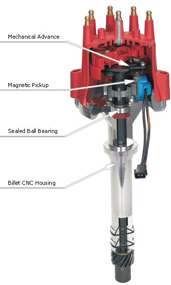
Distributor Operation
The distributor of a typical engine has a lot more responsibility than just distributing the spark to the correct cylinder (which in itself is a feat). It is also triggers the coil to release the high voltage, in many cases it turns the oil pump, it distributes the spark to eight different cylinders and it alters the timing of the system. The distributor could be the hardest working part of your ignition system and this is why it is important to ensure that your distributor is up to the task of delivering the performance and power that you expect from your engine.
Distributors have changed over the years. From plastic to billet housing materials, trigger mechanisms, timing controls and other items have all been modified over the years, yet most models will perform some if not all of the following duties:
- Distribute the spark to different cylinders
- Trigger the secondary side of the ignition
- Alter the ignition timing
- Driving the oil pump
Most distributors are driven by the camshaft through gears with a one-to-one ratio. (This means the distributor turns at camshaft speed, or half of crank speed.) There are a two important parts attached to the shaft; a trigger wheel and the rotor. The trigger wheel will vary depending on the type of trigger being used, but you will notice that it will have a tooth, or lobe or space for each cylinder of the engine. The rotor delivers the high voltage from the coil to the correct cap terminal. When the coil fires, the voltage is transferred through the coil wire to the center terminal of the distributor cap. This terminal contacts the center of the rotor, moves across the rotor and jumps across a small gap to the spark plug terminal of the cap. All of this occurs in fractions of a second and thousands of times.
Timing Settings
Timing Settings
As your engine rpm and load varies, so does the need for your timing. At idle, a spark occurs on a piston’s compression stroke a few degrees before it reaches TDC. At this point, the fuel mixture is ignited beginning the combustion process. The act of combustion remains fairly constant but because the piston is travelling at a much higher speed, the initiation of the combustion process needs to occur sooner. Therefore the spark must occur more earlier in the compression stroke to generate the best combustion and power results. To meet these demands, distributors are equipped with an advance mechanism that operates through centrifugal force.
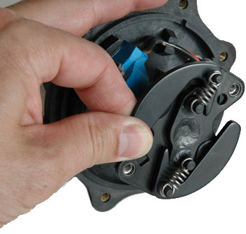
This mechanical advance assembly is made up of two weights that are pushed out by the spinning force of the distributor. Springs are attached to these weights to control the rate at which they are forced out by the spinning motion. The weights are mounted on an advance plate which is attached to the trigger assembly of the distributor so it moves forward resulting in the ignition being triggered earlier (advanced).
By swapping different tension springs you can alter how quickly the timing advances. A spring with less tension lets the weight spin out easier to advance the timing quickly. Many companies offer advance kits that consists of different weights and springs to fit a variety of distributors so you can dial-in an advance curve to match your engine’s needs.
The mechanical advance is an important element is tuning your engine. A slow advance can hinder performance while too much advance can cause pre-ignition resulting a loss of power or even engine damage. This is why it is important to check the timing at idle and at higher rpm so you know what the total advance is at.
The advance assembly is mounted on top of distributor shaft on all of MSD’s distributors which makes changes even easier. To stop the amount of advance, there is a stop bushing under the advance plate that can be replaced. This way you have better control, and an easier time adjusting, over the total timing.
The operation of a mechanical advance assembly is based on the physics of centrifugal force. As the distributor spins, the weights overcome the tension of the springs and push out from the center of the distributor. This movement advances the trigger function of the distributor, therefore the timing also advances.
Timing Terms
There are three timing terms you’ll hear during bench racing sessions; Initial timing, mechanical (or centrifugal) advance, and total timing.
Initial timing refers to where the timing is set at an idle. This is also where you position the distributor when setting the timing. Generally, this will be 6° or 12° or something lower, depending on the application.
Mechanical timing refers to the amount of advance that the weights, or advance assembly add to the initial. For instance, a distributor may be set up to supply 21° of centrifugal advance.
Total timing is the term given to the highest amount of advance. This is when the initial timing is added to the mechanical timing. For instance, if an engine has 10° of initial combined with 21° of mechanical, the total timing is 31° BTDC. Note that Total timing never includes vacuum advance.

This chart shows a typical timing set up with the initial set at 10° with the centrifugal advance starting to move at about 1500 rpm and reaching total timing 28° at 3500 rpm. (Meaning an 18° timing advance curve.)
Vacuum Advance
Vacuum advance is primarily used in an effort to improve economy, therefore you won’t hear much about vacuum advance when discussing performance and racing. There is little to no vacuum during wide open throttle which means no vacuum advance any way!
A vacuum advance canister provides a way to advance the ignition timing during moderate and part throttle conditions. This is when the load on the engine is less and vacuum is higher. There is a diaphragm inside the canister which is connected to a linkage connected to the pickup plate in the distributor. When vacuum is applied, the plate is pulled which advances when the trigger signal is created. When the engine accelerates, vacuum drops so the advance returns to the original position.
When connecting the vacuum advance, most applications connect to a port above the throttle plates. This is called ported vacuum compared to manifold vacuum which comes straight from the intake manifold. The difference here is that manifold vacuum is there constantly while the ported source provides vacuum only when the throttle blades are open. The amount of advance that occurs varies by application but generally ranges from 10°-15°. Some companies even offer an adjustable vacuum advance canister. This lets you set the exact amount of vacuum advance that your engine requires.
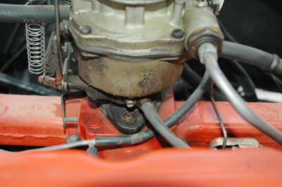
Most vacuum advance canisters are connected to a ported vacuum source (above the throttle plates on a carburetor). This way, there is only advance when the throttle is being applied.

Some aftermarket vacuum canisters are adjustable through the vacuum port.
Tools and Resources
Timing Lights

As with most tools, there are several versions of timing lights available, and they can range from cheap to upwards of a couple hundred dollars. When you’re shopping for a light, ask yourself what you’re looking to accomplish along how much you can spend. If you’re only going to be setting the timing occasionally on your street machine you may not need the super cool light with the latest gizmos and gadgets. If your engine strives on timing changes within a half a degree, stepping up to better quality may be required.
MSD offers a couple different timing lights; a Standard Light and a Self Powered Light. Both have removable leads (for safety and storage) with clamp on pickups. The nice thing about the Self Powered version is that it doesn’t need to be connected to the battery.
Timing Tapes

You can have the brightest, most accurate timing light available, but if you don’t have a clear timing mark on the balancer or pointer, it’s not going to do you any good. Stock balancers will just have a timing line stamped at the TDC point for the number one cylinder, so there’s not much of a chance to check the total advance. MSD offers a Timing Tape PN 8985 that you apply to the balancer so you can accurately check the total timing of your engine.
Timing Curves
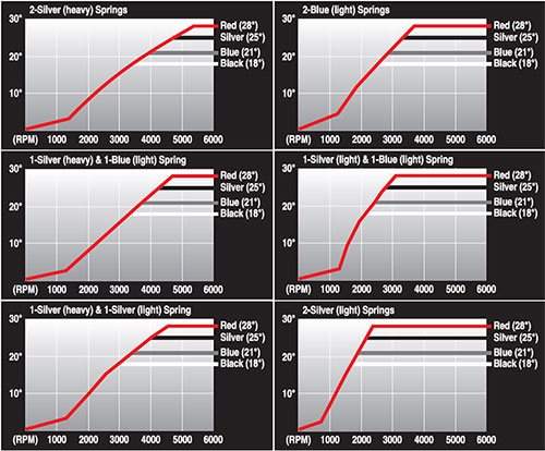
Timing Curves
The charts below show the variety of timing curves available on an MSD Distributor simply by changing the advance springs and stop bushing.

FAQ

 Get help from other Gear Heads!


Back To Top